Pneumatic
You write: I don't think the PRE-Junker engine will ever be useful for a car or motorcycle, as it is too wide for it's capacity. It is simply the wrong geometry to be practical.
A 500cc Junkers-PRE engine (50+50=100mm stroke, 80mm bore) has a maximum dimension of 557 mm
The power and the torque of this engine are close to those of a conventional 1000 cc four stroke.
I measured the width of the Honda Civic VTEC engine. This engine has at its top a width of about 530 mm (670 with the distributor). This engine has also a depth of about 240 mm and a height of about 540 mm (if you can please please let me know the Hayabusas engine dimension).
In case of twin Junkers-PRE (i.e. two cylinders sharing the same crankshafts (having crankpin at 180 degrees for even firing) the maximum dimension of the Junkers-PRE remains at 557 mm while it becomes 1000 two stroke cc in capacity. I.e. more powerful and more smooth than the civic 1600 straight four. The rest dimensions of the Junkers-PRE are beyond comparison.
The compactness and the external form of the Junkers-PRE are advantages not drawbacks.
Compare the Junkers-PRE 500 cc with BMWs Boxers 800 cc or 1000cc: the one is like the mother of the other, in all dimensions. In case of Junkers-PRE the engine could be mounted on a motorcycle even longitudinally as a part of the frame (this for Kingofthering).
You write: I don't think air cooling will work with this layout, because the gears are in the way of the air flow.
You'd either need some complex shrouding, or to move the gears to the lower side.
I actually don't think air cooling will work at all, because as the center part of the cylinder thermally expands, the crankshafts move further apart and the gears will lose their mesh. I think Junker had a similar problem in his earlier engines.
I think you need a more rigid outer casing with water cooling to keep the expansion under control. Or you need a rigid case to run around the cylinders to the crankshafts, and let the cylinders grow in towards each other. Or you need to get rid of the gear connection and use a chain / belt with a tensioner. There are lots of options, but they all effect the size and practicality of the final design.
The synchronizing gears is preferable at the top, close to the rotors. The four stroke lubrication helps here: the gearing case has oil that can cool the cylinder below as necessary. Many Suzuki aircooled motorcycle engines use the air-oil cooling.
As for the thermal expansion:
The thermal expansion was a problem for the typical Junkers PRE because the distance of the two crankshafts was huge compared to Junkers PRE. The typical Junkers long gearing had also to carry half of the power to the output shaft. The gearing of Junkers-PRE carries no power.
On the other hand, The synchronizing gears in the plot above are not in line. If you keep their centers at constant distance, no matter how much the distance of the crankshaft enlarges, their operation remains correct. But this is luxury.
You write : Having opposing pistons gave thermodynamic advantages back in the 30's, but I don't think the advantage is as significant these days. There are better ways to reduce thermal losses through the cylinder head, like ceramic coatings and even ceramic engine parts. Ceramic coatings on piston crowns, combustion chambers and valves are very common performance modifications.
I hear about adiabatic engine for some twenty years now. If they succeed, the Junkers-PRE will also take advantage of them. Today they are not in use despite the vast amounts of money that have been spend on this technology. Their investors know.
You write: I think the one-way valves will be troublesome and difficult to to control. If they don't close in time they will hit the piston. Reed valves on a normal two stroke can stay open at high rpm with no problem.
What will the one-way valves be made from, and how will they have a spring force applied?
The existing reed valves of the two stroke motorcycles are more than adequate for the Junkers-PRE as they operate reliably over 15,000 rpm.
By the way take a look at some other kind one way valves at
http://www.pattakon.com/vva/VVA_Idle/VVA_Idle.htm
You write: The "exhaust" side (not a very good name, but you should know what I mean) will pose problems. There is no room in the port for it to open. It needs a space to fold back into.
Sorry, be more specific. I dont understand.
You write: Starting the device by the propellor will be hard. Since there is no guard, you can't sit it in the ground and crank it over. You need to hold the entire machine over your head with one hand, and crank it over by the propellor (which is probably out of reach) with your free hand.
OK, here is a problem. Maybe something like a kick starter.
You write: As for efficiency, two-stroke petrol engines are not as efficient as two-stroke diesels. In a two stroke you get good power when you get to the point that some of the intake charge completely flushing the combustion chamber and starts to go into the exhaust (before the compression stroke). On a diesel engine this is fine because a diesel is direct injection, and only injects the fuel it needs. Therefore by wasting intake charge out the exhaust you only waste air, not fuel.
If you inject fuel (petrol) into the intake port, then losing intake charge out the exhaust is inefficient. If you use direct injection petrol you still need to figure out how much air is in the combustion chamber to inject the correct mixture of fuel. It is hard to do if some goes out the exhaust.
So two-stroke intake/exhaust timing and efficiency generally only go together in diesel engines. A diesel would be too heavy for the flyer.
What we actually think is to use in the flying machine Diesel Junkers-PRE for the sake of fuel economy. I hear you saying but the additional weight. If the fuel weight can be reduced more than 3 Kp, the take off weight will be less than using petrol. Junkers-PRE can operate at lower compression than normal Diesels because of the dwell at TDC.
If it was the typical Junkers, the Diesel cycle would have a marked increase on engines weight. In case of the Junker-PRE the two close to each other crankshafts make the bending moments on the cylinder weaker etc etc. So all you need is a reinforced cylinder and two stronger crankshafts.
If direct petrol injection is used, the lambda sensor gives the feedback to the EFI and the injection duration is adjusted as in the present car. When the Pattakon Civic prototype uses closed loop control, it automatically reads the Oxygen concentration at exhaust and adjust the injection duration.
You write: Some interesting info on the junker;
Quote:
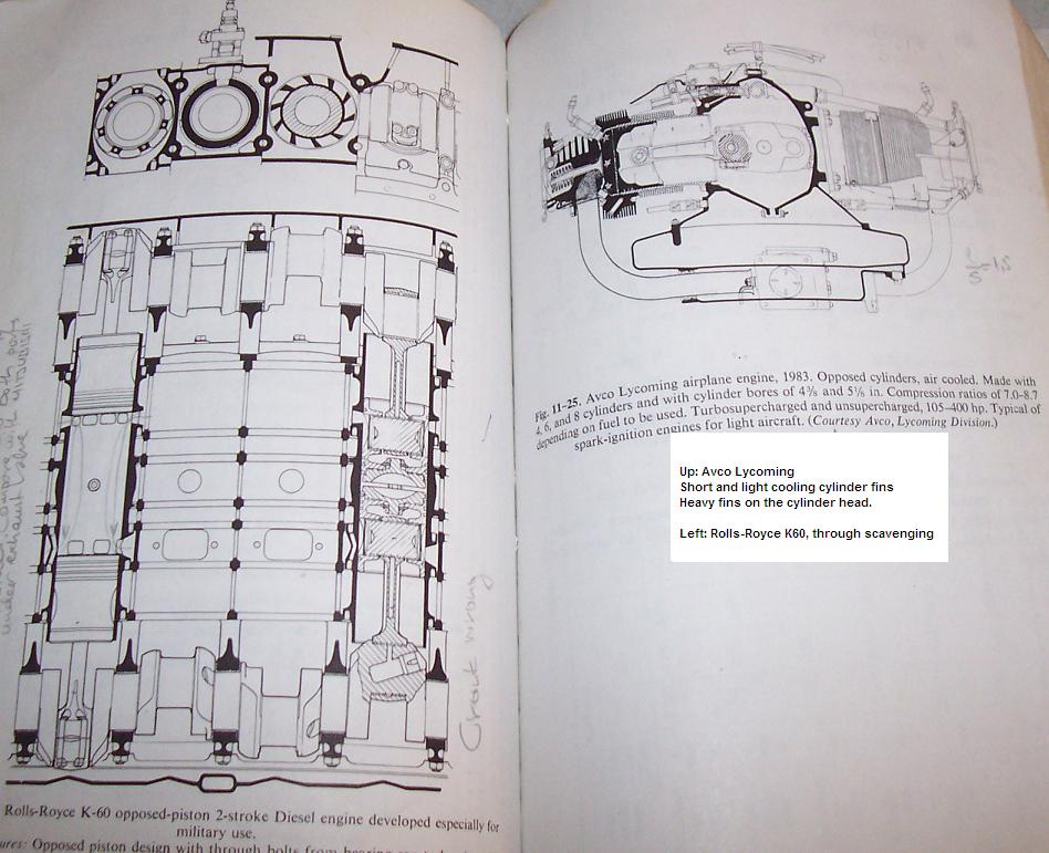
The Junkers aircraft 2-stroke diesels comprised 6 in-line vertical cylinders, 12 pistons and 2 crankshafts coupled by a gear train, also used for the propeller reduction gear. The lower pistons opened the intake ports, the upper ones opening the exhaust ports. In order to get the optimum timing, the lower (intake) crankshaft was about 11° retarded relative to the upper exhaust one. So the latter received roughly 3/4 of the power and it was geared directly to the propeller shaft.
I'm sure retarding it 11degrees didn't do much for the balancing either.
If the absolute balance is necessary, the asymmetric timing is not the case. If necessary, a clap at exhaust can offer the control.
If the asymmetric timing is advantageous a little vibrations is the price.
In the flying machine it is better to have Diesel cycle with absolute balance.
Thanks
Manolis Pattakos


 Reply With Quote

 , but from first glance the conrod forces don't look balanced.


 . Using two cams for 4 pistons should be able to offer weight and space saving.