Page 12 of 98 FirstFirst ... 210111213142262 ... LastLast
Results 166 to 180 of 1461

Thread: A work of pure genius! - Brilliant "Revetec" Engine

  1. #166
    Join Date
    May 2003
    Posts
    99
    Quote Originally Posted by revetec


    I measured the graphic roughly and worked out it was using a 1.375:1 reverse conrod ratio. Is this graph roughly right? If not right please someone else do it and I'll remove mine.

    Comments in regards to breathing and power stroke differences this would cause? A torque lever graph would be useful too...Can anyone do one and post it?

    Brad,

    Your plot seems almost right now.
    I think it is easier to think about the breathing ‘difficulties’ of the PRE engine not through the piston acceleration plot you use now, but through the piston travel plots.

    In the plot below what you see is the piston travel versus the crank angle for a conventional engine, the PattakonPRE (both using conrod to stroke ratio equal to 1.65) and the Harmonic or pure sinusoidal engine.


    If the conventional is revving at 1.35 times SLOWER than the PRE (for instance the conventional is revving at 5600 rpm while the PRE is revving at 7500 rpm), then around TDC the working medium (air or mixture) cannot see any difference. The orange curve in plot below is (around TDC) identical to the blue curve of the PRE.


    If the conventional is revving at 1,35 times FASTER than the PRE, then around BDC the working medium cannot see any difference again. The orange curve in the plot below is (around BDC) identical to the blue curve of the PRE.


    So the PRE as regards TDC is nothing but a conventional revving at significantly slower revs, and as regards the BDC, the PRE is nothing but a conventional revving at significantly faster revs.

    It is obvious that the valve lift profiles (if valves are used) have to be change to suit to the PRE piston motion, as well as the spark advance (or the injection advance in case of Diesel). If necessary, the PRE can use Pattakon’s Variable Valve Actuation (or VVA) system in order to optimize breathing along the whole rev range (you can see details for this breathing system at http://www.pattakon.com/ ).

    In the animation you measured a con-rod to stroke ratio equal to 1.35 but as you understand there is no any limit. As always it is a matter of compromise.

    Thanks
    Manolis Pattakos

  2. #167
    Join Date
    May 2003
    Posts
    99
    Quote Originally Posted by pneumatic
    By changing the phase you also change the relationship between the intake and exhaust port timing. But the problem with having them out of phase is vibration.

    And added a few gears on looks fine in a concept 3D model, but once you added bearings and other items to support it all then the concept starts to look not so simple.
    Pneumatic

    The Junkers-PRE engine is an absolutely balanced engine as regards inertia forces and moments. If in this completely balanced engine the phase of the crankshafts is changed a little, the vibration will still be less than in a conventional having the same number of pistons. The ability of the Junkers-PRE to change the compression ratio is nothing important compared to its rest advantages. It was mentioned as it is in fashion these days and it is easily achieved with PRE.

    The synchronizing gears is not a big deal.
    Using the PRE for a motorcycle it would be necessary a gear primary transmission. Doesn’t the Yayabusa have a primary transmission with gears? In the PRE this necessary primary transmission is also the synchronization equipment.
    So, what is the added complication?

    Thanks
    Manolis Pattakos

  3. #168
    Join Date
    Sep 2006
    Location
    Brisbane - Australia
    Posts
    69
    Quote Originally Posted by manolis
    The synchronizing gears is not a big deal.
    Using the PRE for a motorcycle it would be necessary a gear primary transmission. Doesn’t the Yayabusa have a primary transmission with gears? In the PRE this necessary primary transmission is also the synchronization equipment.
    So, what is the added complication?
    It is not a big deal, and can be done. I am just saying by the time you add the supporting bearing and everything the engine isn't as compact as it first looks in the images you posted.

    The primary drive between the crank and the clutch basket on a motorcycle engine is relatively compact, because one gear is counterlevered off the crankshaft which is already well supported and stiff. The clutch basket gear is counterlevered off one of the gearbox shafts so it is also already supported and stiff.

    I wasn't saying it's hard, I was just saying it's not quite as simple and compact as drawing a few gears on the side.

  4. #169
    Join Date
    May 2003
    Posts
    99
    Quote Originally Posted by pneumatic
    It is not a big deal, and can be done. I am just saying by the time you add the supporting bearing and everything the engine isn't as compact as it first looks in the images you posted.

    The primary drive between the crank and the clutch basket on a motorcycle engine is relatively compact, because one gear is counterlevered off the crankshaft which is already well supported and stiff. The clutch basket gear is counterlevered off one of the gearbox shafts so it is also already supported and stiff.

    I wasn't saying it's hard, I was just saying it's not quite as simple and compact as drawing a few gears on the side.
    Pneumatic,
    I still try to get the difficulty.
    In Junkers-PRE
    which is the only PRE that needs synchronizing gears (I hope you saw the rest PRE arrangement animations at http://www.pattakon.com/pre/index.html )
    you have an already well supported and stiff crankshaft (as in any conventional motorcycle engine) and a primary gear secured to it (the primary gear could also be cut directly on crankshaft's material).
    The Junkers-PRE clutch basket gear is rotatably supported on the block of the engine (it could alternatively be rotatably supported on the gearbox casing too: because Junkers-PRE has a gearbox too).
    I can't see any added complication.
    Do I miss something?

    Yamaha ungrudgingly uses gears and additional counterbalancing shafts in its TDM model just to counterbalance the 1st order inertia forces. And BMW ungrudgingly increases the width of their R motors to get the benefits of the boxer arrangement. I guess Hayabusa, as all big straight four like Honda and Kawasaki - uses one or two second order counterbalancing shafts (and the necessary gearing and bearings) to cancel the second order inertia forces. Just compare their 'simplicity' and their 'balance' to Junkers-PRE.

    Thanks
    Manolis Pattakos

  5. #170
    Join Date
    Sep 2006
    Location
    Brisbane - Australia
    Posts
    69
    The outside gears are not a problem. It's the center gear. I have made a sketch to make it more obvious. It won't be very reliable how it is shown in the image below. For that to be possible, the center gear would have to be cantilevered off a single bearing behind the gear (between the gear and the cylinder). This will be very unreliable and/or would lead to a large bearing design. Really it needs a second bearing. You can't set it up like the crankshafts (a bearing either side of the cylinder) because then you'd have a shaft through the combustion chamber. And if you put one in front of the center gear then it can't have a clutch plate in it, because you wouldn't be able to get the clutch plate out.


  6. #171
    Join Date
    May 2003
    Posts
    99
    Pneumatic,

    It is not a problem.

    If your argument is correct, i.e. that the center gear does need a pair of bearings at a reasonable distance, then instead of using a shaft penetrating the combustion chamber, it is more simple and functional to move the center gear lower or higher, thereby the supporting ‘necessary’ long shaft with the two bearings to pass outside the combustion chamber. This way the primary shaft of the gearbox can be located lower or higher (whatever seems better) than the crankshaft axes, while the synchronization of the two crankshafts is as good as before. The drawback : a little larger gear diameter.

    These in theory, because things are much simpler and easier as you will see in the following.

    In my previous reply the Yamaha TDM was mentioned and here is a photo of TDM’s internals.


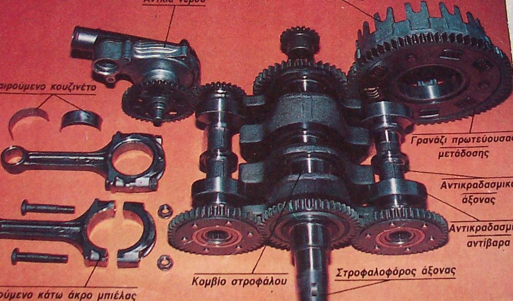
    In this photo what makes impression is the ‘complication’.
    Count the additional shafts, gears, shock absorbers, bearings and imagine the additional weight, cost, faults and friction. And all these for what? Just to balance the 1st order inertia forces!

    In the sane photo one can also see that the clutch basket gear is rotatably supported on a unique bearing (which seems less than 20mm wide). Why so simple? Because the loads it carries do no need something more. If this basket gear had to be used as the center gear in a PRE-Junkers engine, all you need is a projection (like an immovable short shaft) from the center of the block. That simple, compact and robust.


    If you still have doubts, just imagine the way a front wheel of a car is rotatably supported to its shaft and then imagine the huge loads – at all directions – the front wheel has to carry.


    And regarding bearing loads:

    The bearing of the basket gear of a conventional motorcycle is heavily loaded: the force applied to the teeth of the basket gear from the teeth of the crankshaft gear generates:
    - a torque that, through the clutch, is transferred to the primary shaft of the gearbox,
    - and a force (equal to the force applied to the teeth of the center gear from the crankshaft gear) that heavily loads the bearing(s) of the basket gear.

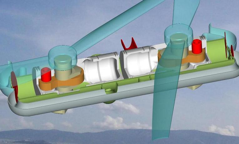
    In the case of the Junkers-PRE the bearing of the center gear remains actually free of loads: the two crankshaft gears apply equal and opposite forces (i.e. a pair of forces) to the center gear (the forces are equal because the two crankshaft share the same instant gas pressure inside the common cylinder), so the center gear’s bearing carries actually nothing. I suppose I could keep the shaft of the center gear of the Junkers-PRE engine by hand.

    Thanks
    Manolis Pattakos

  7. #172
    Join Date
    Sep 2006
    Location
    Brisbane - Australia
    Posts
    69
    All I am saying is that it isn't as simple as shown in that image. And it isn't. That is all I am saying.

    The motorcycle examples are totally different because you don't have a main component anywhere that is supported by a single cantilevered bearing. The motorcycle clutch basket has the bearing inline with the teeth, but the image above of the PRE-Junker doesn't (as the clutch plate is shown inline with the teeth).

    My original quote was "The not so pretty part is connecting the two cranks together to keep them in synch". And it was in regards to the following picture;


    I was just saying that the picture above makes the engine look really really simple. But in reality you need to connect the cranks, which obviously makes the design bulkier. That is all I was saying. I didn't say it was hard to do, or couldn't be done.
    Last edited by pneumatic; 10-22-2006 at 04:11 AM.

  8. #173
    Join Date
    May 2003
    Posts
    99
    Brad,
    here is the plot for the acceleration of the PRE with 1.375 con-rod to stroke ratio


    Thanks
    Manolis Pattakos

  9. #174
    Join Date
    May 2003
    Posts
    99
    Quote Originally Posted by pneumatic
    All I am saying is that it isn't as simple as shown in that image. And it isn't. That is all I am saying.

    The motorcycle examples are totally different because you don't have a main component anywhere that is supported by a single cantilevered bearing. The motorcycle clutch basket has the bearing inline with the teeth, but the image above of the PRE-Junker doesn't (as the clutch plate is shown inline with the teeth).

    My original quote was "The not so pretty part is connecting the two cranks together to keep them in synch". And it was in regards to the following picture;

    I was just saying that the picture above makes the engine look really really simple. But in reality you need to connect the cranks, which obviously makes the design bulkier. That is all I was saying. I didn't say it was hard to do, or couldn't be done.
    Pneumatic,

    OK, from now on instead of saying 'it is really really simple', we will say 'it is really simple' or just 'it is simple'.

    I hope you agree that the center gear of the PRE motorcycle engine (i.e. the PRE13.exe animation) can be rotatably supported on a projection (i.e. an immovable very short pin) at the middle of the block and that this support is very light, really robust and involves no complication.
    Sorry if in the animation it is not clear that the teeth of the gears are in the same plane with the bearing of the center gear. But this is 'the' reasonable selection for the location of the bearing, so I supposed it was obvious. I was wrong.
    In any case the animations in the pattakon site are made to show, in the international language of pictures, the general idea and not the details.

    I would prefer to have your comments on the substance of the PRE idea. Please write your objections.

    By the way, take a look at
    http://www.pattakon.com/fly/Flyer4.exe
    and
    http://www.pattakon.com/fly/Flyer5.exe
    animations added these days to pattakon site.

    Thanks
    Manolis Pattakos

  10. #175
    Join Date
    Sep 2006
    Location
    Brisbane - Australia
    Posts
    69
    Quote Originally Posted by manolis
    Sorry if in the animation it is not clear that the teeth of the gears are in the same plane with the bearing of the center gear. But this is 'the' reasonable selection for the location of the bearing, so I supposed it was obvious. I was wrong.
    In the image below, there is a clutch and pressure plate in the middle of the center gear, inline with the teeth. So the "reasonable selection for the location of the bearing" cannot be inline with the gear teeth, because there is a clutch plate there. So it must be cantilevered off a bearing at the back, which would be a bad design.


    I know the images are concepts, and because of that they are not worth discussing. It is easy to make a concept, it is hard to figure out all the details and still have a good design.

    The Revetec concept is fine, but the details shown thus far haven't been very impressive. It sounds like they are working through the details and making progress, so the final design may still be good, but until then there isn't much point commenting.

    Take the flying machine concept. It shows the handle bars out in front of the propellers. That wouldn't work, the handle bars need to be inline with the propellers - which is easy enough to fix.

    The concept animations make it look very simple, but when you add all the other bits needed to make it work you realise the actual product would be much much bulkier. For it to be a detailed design, they need to add;
    * A fuel tank
    * Carb's or EFI
    * A starter motor (or starting device)
    * a battery
    * an alternator / generator (which has to be run off the crankshafts)
    * cooling. air cooled fins will make the design much bulkier. water cooling needs a water pump and radiator
    * spark plugs, probably 2 (one each side of cylinder)
    * ignition system, leads, coil, something to time the spark
    * guarding for the fans (as they slow down the machine will want to fall onto the ground unless you are strong enough to hold it up until it stops)

    So you can see the animations they show are rather pointless. They only show a very simple concept. It will still have vibrations. Although the pistons balance each other, the conrods will still produce unbalanced vibrations.

    To be honest I don't see the point of having the outer piston halfs. Normal two strokes get by just fine using the underside of the firing piston and crankcase to do the same job.

    I think a conventional pair of two stroke engines set up so the pistons face each other would probably be better. The advantage of running the two stroke fuel/oil premix through the crankcase is that the premix lubricates the bottom end very well, and cools the piston.

    On the PRE-junker the second piston will try to keep the fuel/oil premix out of the crank area. So from what I can gather they are going to use an oil ring and lubricate the crank with engine oil like a 4 stroke engine (advantage is they don't need premix oil). So now you probably need to add an oil sump and oil pump to the list of parts required for the engine. You also have to make sure you don't get too much oil around the cranks, or you will have a lot of power loss due to oil being flung around under the pistons.

    So you can see when you start getting into the detail, then the problems with the design will come out.

    I am not saying any of it can't be overcome, but I am saying that those animations are deceiving because they make it look really simple.
    Last edited by pneumatic; 10-22-2006 at 04:07 PM.

  11. #176
    Join Date
    Nov 2005
    Location
    Gold Coast, Australia
    Posts
    581

    Conrod ratio

    Dear Manolis

    Your graphs seem to look ok but we have discussed on here previously that a longer conrod ratio is for higher revving engines such as F1. If you look at the graph 1.65:1 is good for 7,000rpm and 2:1 is good for 18,000rpm so what type of characteristics will you get from such a piston acceleration curve?

    My point is that an engine running such an acceleration curve must make it only suitable for a lot greater than 18,000rpm? Doesn't it?

  12. #177
    Join Date
    Nov 2005
    Location
    Gold Coast, Australia
    Posts
    581
    Not really a fan of the way the pistons separate. But I suppose they may come up with alternative designs....

    My "bearings" point on the GRECO engine was that if you separate the shafts so they don't hit and the bearings are made at a size that is reliable and those components will not fit up the bore unless the engine is very very oversquare. At that point they'll have trouble getting the piston out the way to open the valves. We'll just have to wait to see how they address it. :-)
    Last edited by revetec; 10-22-2006 at 10:56 PM.

  13. #178
    Join Date
    Nov 2005
    Location
    Gold Coast, Australia
    Posts
    581
    Dear Pneumatic,

    I agree with your comments on the bearings on the output shaft of the Pattakon engine. These gears are necessary and it'll be interesting to see how they get it all to work and what the prototype will look like and vary from the concept shown.

    I suppose your comments on our engine will be a bit different once our website is updated and our new design is shown. :-)
    Last edited by revetec; 10-22-2006 at 11:04 PM.

  14. #179
    Join Date
    Oct 2006
    Location
    Melbourne
    Posts
    51

    When will web site be updated?

    When will your web site be updated?

    What date are you expecting it to be ready so that we can all have an open discussion on the merits of the technology.

    Regards
    SPT

  15. #180
    Join Date
    Sep 2006
    Location
    Brisbane - Australia
    Posts
    69
    Quote Originally Posted by revetec
    I suppose your comments on our engine will be a bit different once our website is updated and our new design is shown. :-)
    I just hope there's enough info there to figure out what's going on this time

Thread Information

Users Browsing this Thread

There are currently 3 users browsing this thread. (0 members and 3 guests)

Posting Permissions

  • You may not post new threads
  • You may not post replies
  • You may not post attachments
  • You may not edit your posts
  •