Page 9 of 98 FirstFirst ... 78910111959 ... LastLast
Results 121 to 135 of 1461

Thread: A work of pure genius! - Brilliant "Revetec" Engine

  1. #121
    Join Date
    Nov 2005
    Location
    Gold Coast, Australia
    Posts
    581
    Dear Pneumatic,

    Firstly that you are quoting old reports that the engine does 6 strokes per rev. The graph you are showing is of a revetec engine that has 2 strokes per rev. You may note that in the pictures that the valve train is running a 3:2 ratio on the belts but what is not shown is the 1:3 to the output shaft as the output shaft on that engine does not protude out of the engine case at the front. Maybe I should get our website design company to update some information that we can disclose to make things clearer.

    Secondly, the engine you are comparing is a high performance engine, not an engine setup for a production car with only fuel economy and emissions in mind. Performance models will evolve but even the valve grind we are using is similar to existing automtive engines that are manufactured with economy in mind. Let's compare the Toyota Prius engine with the 1.3L Suzuki Hayabusa engine. Or the sukuki engine with a F1 engine. They are as different as the comparison you are making so it is meaningless. We have compared our engine to the prius engine (Minus hybrid) and the vectra engine that is currently in production. Two engines that provide good fuel economy.

    Does your suzuki engine feel as powerful at 1,500rpm as 6,000rpm? Your engine feels most powerful (best acceleration) where the torque peak occurs. At 6,000rpm you are using 3-4 times the fuel to accelerate the same. Have you ever seen a BMEP pressure map and then compared it to a mechanical efficincy graph. It is funny to think you believe that the peak pressure is only at the same point of a crankshaft's maximum efficincy point and there is no pressure on the piston at any other point. Fuel mixtures, load and rev range vary the peak pressure's postion. Ignition timing get's the pressure point as close to this position but has limitations to the amount that can be used due to detonation and the like. If you were to graph the above mentioned at the maximum point you will realise that the losses are around 36%. It is far worse at lower rpm's and at a partial throttle, where most driving occurs. Please find the thermal efficiency figures of the suzuki engine at a varying load and rev range, especially at the point where most operation occurs. The proplem occurs in evaluating an engine when the peak power is considered.

    A friend of mine had a truck which had high torque at low revs which he replaced with another with higher power. He found that the new truck had to be revved higher to produce the power. Fuel economy was worse under the same operation conditions and he felt he had to abuse the engine to gain the same performance with the same load. This is why a large torque band in a lower rev range is so important.

    I'm not having a go at you. I'm just trying to explain why we are doing what we are doing. There are many things that we have experienced in our testing we are still trying to fully quantify, such as when we program an engine fuel injection on the dyno that the fuel injector duty cycle reduces when the revs and load are increased. This has never been seen in an engine before and it will take many years of analysis to fully understand what we have experienced in hard tests. All I can say is that we have had to take engines OS to prove the torque and fuel delivery maps under independant testing by because it seems impossible to engine manufacturers that we are talking to. They have to see it with their own eyes on their own equipment. This has been done.

    Regards
    Brad Howell-Smith

  2. #122
    Join Date
    Nov 2005
    Location
    Gold Coast, Australia
    Posts
    581
    Dear Pneumatic,

    So let us refer to your graph before you put the gearing factor in which is incorrect due to the fact that those figures were produced on an engine with 2 strokes per rev being the same as the compared engine. We are producing more power in the normal automotive rev range and producing almost the same peak torque at 3,500rpm compared with 6,500rpm of the 1.3L Suzuki Hayabusa engine, when the fuel usage would probably be double. Note again that the lower the revs that the torque is applied the better. This is an automotive vehicle engine prototype. Knowing this I think you would be silly to say that our engine doesn't save fuel dramatically in an automotive application. Maybe in the future we we develop an engine that has the same application as the Suzuki Hayabusa engine. The figures would be very interesting due to providing engine breathing at the same RPM and extending the flat torque curve to a higher RPM range. We actually produced a better and dead flat torque curve very recently at a leading engine manufacturers facility. Our next engine will even be better.

    Last edited by revetec; 10-03-2006 at 09:03 PM.

  3. #123
    Join Date
    May 2003
    Posts
    99
    I came across this thread today.

    Please take a look at http://www.pattakon.com/greco/index.html or start from http://www.pattakon.com
    and select either the ‘GRECO animations’ or the ‘GRECO theory’ topics. There are some 20 animations.

    Then forget all about crankless engines, return to the present conventional TESTED technology and take a good look at http://www.pattakon.com/pre/index.html (or get into pattakon's site and select the Pulling Rod Engine – NOT the Pulling Piston Engine which is its father – ).
    If you have to select just one animation of the Pulling Rod Engine, try the http://www.pattakon.com/pre/PRE13.exe or
    http://www.pattakon.com/pre/PRE14.exe or http://www.pattakon.com/pre/blueprint.pdf .

    Thank you
    Manolis Pattakos

  4. #124
    Join Date
    Nov 2005
    Location
    Gold Coast, Australia
    Posts
    581
    Dear Manolis,

    Re: Pull rod engine

    Unless you are doing formula1 RPM's (18,000RPM) a conrod ratio of around 1.65:1 is desireable to achieve the correct piston acceleration. The higher the RPM's the higher the conrod ratio required. A normal car is around 1.6:1 - 1.7:1. Is this Pull rod configuration engine a automotive production engine or a 18,000RPM one? If it is aimed at the car market then:

    This company doesn't know anything about breathing. Any engine of this kind has a slower initial piston speed which decreases the initial gas flow past the valve. We have investigated using a cam with a perfect sine wave in piston acceleration and we have found that any engine with a con-rod to stroke ratio of anything over 1.7:1 reduces breathing and requires supercharging at lower RPMs or non standard valve timing when getting over 2:1. The problem with many people is that they don't understand engines properly and even though some theory may look good and the design looks simple, doesn't mean there are no inherant problems with what they are trying to do.
    BTW. Let's see an actual engine run with figures of this pull rod engine.

    Brad
    PS. I modified my response so as not to be so agressive as I think I went overboard and was probably having a bad day reading all the threads. Sorry If I upset anyone! :-)
    Last edited by revetec; 10-19-2006 at 07:26 PM. Reason: Not clear enough.

  5. #125
    Join Date
    May 2003
    Posts
    99
    Dear Brand,

    Thank you for your reply.

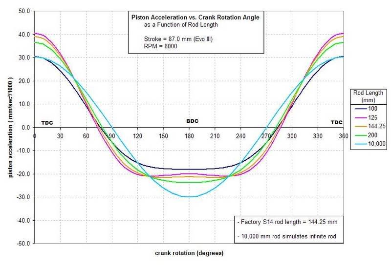
    You wrote : This company doesn't know anything about breathing. Any engine of this kind has a slower initial piston speed which decreases the initial gas flow past the valve. We have investigated using a cam with a perfect sine wave in piston acceleration and we have found that any engine with a con-rod to stroke ratio of anything over 1.7:1 cannot breathe properly and requires supercharging.

    It seems you never heard that all Formula1 and GP-moto engines use con-rod to stroke ratio well above 1.7:1 (most above 2.0:1). And they do not use supercharging. It seems they know nothing about breathing (AND combustion).


    You wrote : The problem with amatures like these people is that they don't understand engines and even though some theory may look good and the design looks simple, doesn't mean there are no inherant problems with what they are trying to do. Companies like this just burn investors money without having any prospect of getting an engine to perform or get to production.

    I declare publicly today, to any one of pattakon’s investors to brink me their shares and I will buy them - immediately - a million times their initial price in US dollars (i.e. for each dollar the investor – any investor – gave, he will take a million dollars in return).

    Pattakon makes the only continuous VVA (variable valve actuation) engine in the world capable of revving over 9000 rpm. BMW do not use their valvetronic VVA system in their sport cars because they cannot.
    We can arrange a test drive for you (or any other professional). Take a look at the http://www.pattakon.com/vva/VVA_Idle/VVA_Idle.htm and the video http://www.pattakon.com/vvar/OnBoard/A1.MOV etc, etc in www.pattakon.com site.

    Once again: I call any professional willing to have a test drive with pattakon’s cars to call me.
    And a special offer – it is the challenge you asked for -for you: come for a test drive in Athens and if you see less than I claim, I will pay your first class airplane tickets.

    Just to find out who is giving the engine development industry a bad name and who is burning investors money.


    You wrote : Let's see an actual engine run with figures of this pull rod engine. You'll never find one now or in the future because in real life it wont work properly.

    I admit, there is no yet a Pulling Rod Engine prototype.
    But take a look at the pattakon’s US patent 6,062,187 and then HONDA’s US patents 6,763,796 and US 6,786,189 ( http://www.uspto.gov/patft/index.html ). It seems HONDA’s staff do not know that con-rod to stroke ratios above 1.7 cannot breathe properly. Please inform HONDA, too, to stop wasting their time over such crap.


    Thanks
    Manolis Pattakos

  6. #126
    Join Date
    Jul 2006
    Location
    Armidale/NSW/Australia
    Posts
    1,047
    what the.........
    people like u dont need to be on this go to supid land where your mind is ass - toyota4ever

    ricers suck...pasta rockets for life - sicilian973-2

  7. #127
    Join Date
    Nov 2005
    Location
    Gold Coast, Australia
    Posts
    581
    Dear Manolis,

    Ferrari F1 engines use slightly greater than a 2:1 conrod ratio but this is to reduce side thrust and allows a lighter piston to be used but most importantly to lower the piston speed down to 24.8 m/s when doing 18,000rpm. Some other formula 1 engines are using down to 1.7:1 conrod stroke ratio and a stroke down to almost 41mm when looking for better performance around the 12,000-15,000 rev range giving similar piston speeds at the desired rpm range. An Evo uses a 1.66:1 conrod ratio which puts the piston speed at maximum acceleration around 20 m/s at 8,000rpm which is a good basis for talking on an on-road application.

    If you look at the piston speed chart below you will see that the sweetspot for good initial piston speed creating good velocity past the valves happens between 1.5:1 and 1.7:1 (130mm and 148mm) at which provide low piston speed at BDC for volumetric efficiency and mid piston speed 18-20 m/s. Above 2:1 initial velocity is decreased and BDC dwell is decreased. The endless conrod theory gives a very slow initial speed and hardly any dwell. The pull rod engine would be even slower in initial velocity and piston speed would be more constant an provide less dwell at BDC.
    Below 1.5:1 the initial velocity suffers also shown in the plotting of the ratio of 1.2:1 which is too low.
    There are many engines that have a conrod ratio above 1.7:1 that perform. Looking at the piston speed graph it would be advantageous to lay around 1.6-1.7:1 if the engine's redline was about 7,000rpm to 8,000rpm

    Changing a conrod ratio also changes the torque application angles of the conrod. Maybe the engines you are referring to are trying to achieve a better drivability by changing the position of maximum mechanical advantagein regards to the point of maximum cylinder pressure on the combustion stroke.

    I have been talking about breathing not about the combustion cycle.

    What you maybe missing from my point is that our engine can utilise the best piston acceleration for breathing while providing the position of maximum mechanical efficiency across the range. This means no matter what ratio is selected for breathing is optimised and independant of the point of mechanical efficiency on the power stroke.

    On some other performance engines the valve timing is wilder or in the Honda's case variable valve timing is utilised. Inefficiencies in breathing caused by selecting a non-optimum conrod ratio can be rectified by using these two mods but if we are talking about conrod ratios as it effects piston acceleration and breathing on two identical set up engines the graph shows the sweetspot.

    I was talking about the pull rod engine and the effects caused by such designs in regard to optimum conrod ratios.

    The chart doesn't lie. It's pure math of a mechanical design of a conrod engine.

    Offsetting the gudgeon pin in either direction from standard type settings also change these graphs. Offset used was a standard Evo.
    Last edited by revetec; 10-08-2006 at 10:08 PM.

  8. #128
    Join Date
    Nov 2005
    Location
    Gold Coast, Australia
    Posts
    581
    Dear Manolis,

    Again Sorry about the agressive post as I was a bit revved up by the threads because everyone was assuming so much without actually knowing the setup used in our last engine, and I jumped in with both feet.

    Let's look at the combustion cycle at 18,000rpm. Such a wide range of rpms would require a longer conrod ratio to work effectivelyas you require to lengthen the band of degrees that the piston is able to transfer power effectively. F1 is hardly the market to compare any on-road engine to.

    I would love to see a pull rod engine run and the figures. I see too many new engines that don't make it to production mainly due to unforseen problems and characteristics. I just like to put it out there and healthy controversial discussion is great because it gets everone thinking. I hope the pull rod engine guys read this thread as it may be of some use to them as it maybe something either they have not thought about due to being early in development or they have some theory other than commonly known in the engine design field. In the latter it would be great to hear their thoughts on this subject. I'd love to hear from them as I might be able to help. I would imagine that the pull rod engine will provide optimum performance at very high RPM ranges going on the probable resulting conrod ratio, but maybe not desirable for automotive use as the piston speed will be very slow initially.

    I still suggest supercharging of this engine at lower RPM ranges due to the low initial piston speeds. I probably wasn't that clear before. I'm always only looking at operating ranges that engines use in mainstream manufacturing.

    Our engine can be easily modified to run any conrod ratio and we have tried a few ratios in our development program using identical setups in the same RPM ranges. We have experienced exactly what the graphs suggest would happen, so it is not just theory, we've done it in practise.

    If you are involved in the pull rod engine, get them to contact me. My contact details are posted at http://www.revetec.com

    PS. Never doubted the benifits of variable valve timing and theirs is probably good.
    Last edited by revetec; 10-08-2006 at 10:26 PM.

  9. #129
    Join Date
    Aug 2004
    Location
    IA
    Posts
    467
    Quote Originally Posted by revetec
    ...
    Something is wrong with "100 mm Rod Length" curve.
    "In theory, theory and practice are the same. In practice, they are not."

  10. #130
    Join Date
    Sep 2006
    Location
    Brisbane - Australia
    Posts
    69
    Interesting thread. I notice some threads such as those by "richy33" have mysteriously disappeared.

    Brad,

    You make many claims, but have no evidence for any of them. So understand that people will be sceptical.

    I am a chartered professional engineer, not some armchair critic.

    The problem I have is with the comments like this;
    I'll also state now that the formulas that work out power and torque do not work on our engine so all of you engineers that are trying to work out figures for our engine, your standard engine calculations will not work.
    That statement is absolutely ridiculous. I am an engineer, so I work in the base metric units. m, rad/s, N*m, W. I don't use any silly formulae that have factors to account for imperial units.

    A force is measured in Newtons.
    A torque is a Force x a radius = Newton.meters.
    Power is torque x rotational speed = Watts.

    There is no arguing this, beause that is by definition what those terms are.

    If you believe it doesn't work on your engine, then you are doing something wrong when calculating these. This I can guarantee. The power and torque must be calculated at the same shaft at that particular shafts rpm.

    We have proven in actual testing our flat torque curve and a flat fuel usage over a varying rev range
    Your published test results so far do not show a flat torque curve, it is no flatter than a conventional engine...

    Another thing is that the fuel consumption remains constant under full load right through the rev range which is not seen in any other engine in the world.
    Well we haven't seen that from your engine either yet, so let's not get ahead of ourselves.

    The "directors announcement" dated 6-Oct-06 states;
    Also noted a further important characteristic aspect namely that our engine at full throttle used the approximately the same amount of fuel at 4,000 rpm as it did at 2,000rpm which was very exciting.
    What do you mean by "same amount of fuel". Is this a fuel flow rate like L/min? Is so this is impossible, unless the torque at 4,000rpm was half what it was at 2,000rpm.

    Has a reliable source actually created a full engine characteristics map for this engine? Did they plot pressure-volume diagrams, brake mean effective pressure, thermal efficiency, specific fuel consumption, etc? I am guessing not as the engine threw a cam-belt during the tests at only 4500rpm.

    It's probably useless trying to discuss this any further for now, because I have made completely logical observations based on the facts and information available so far.

    You have made unproven claims.

    If you want to clear some things up, then let's do so.

    I'll tell everyone now that the cylinder heads are operating at the same speed as a conventional engine. ie. The pistons stroke 2 times (1Xup and 1Xdown) per output shaft revolution (the same as a conventional engine),
    In order to achieve this, your output shaft must be essentially geared up at a 3:1 ratio, so the output shaft spins 3 times faster than the tri-lobe. Is this correct?

    Don't get me wrong here, I am all for new technologies, especially when it is Australian. But some of the claims so far are pretty wild, particularly when there is no proof what so-ever of any of the claims.

  11. #131
    Join Date
    Oct 2006
    Location
    Melbourne
    Posts
    51
    Pneumatic

    You have raised some very interesting points, backed up by facts & sound engineering logic.

    I think you are being a little unfair with Brad, it is obvious that he cannot disclose certain information. He has both hands tied-up and you are throwing all the punches. I have a strong feeling that when his hands are untied, he will strike the strike the biggest blow; just give him time and I am sure he will reveal all.

    Now, I am not an engineer, I am a business person who invests his time in biotechnology. However, I have been tracking this Revetec invention for quite some time. One thing I do know is that a company with the credentials and clout of Mahnindra and Mahindra would not be wasting their time if this technology was not worth their while.

    Mahindra has a great deal to benefit from integrating this technology within their product line-up. India is the fifth largest Asian automotive market and has the capability to tap into China's automotive market which is reportedly the world's second largest automotive market. Mahindra are massive and their engineers seem to have a different perspective to this technology then that posted by you.

    My point here is that, as Brad noted, let’s be patient and stop asking questions which you know Brad is not able to answer due to intellectual property disclosure implications.

    If Brad can introduce a technology that can extend our current oil resource until which time hydrogen fuel cell technology can be utilised practically and logistically (i.e. it may be 40-50 years away) then we should all try and support him.

    You seem to have a very deep understanding of engine technology, can I suggest that both Brad and you get together and share some notes?

    Brad, you are based in the Gold Coast and Pneumatic you are in Brisbane; you are only 45 minutes away from each other. Brad, I am sure you could benefit greatly from Pneumatics input (and I am sure that he/she) will be happy to sign a non-disclosure statement.

    What do you both say?

  12. #132
    Join Date
    Nov 2005
    Location
    Gold Coast, Australia
    Posts
    581
    Dear Pneumatic,

    Our engine transfer characteristic is that the formulae on power and torque uses a constant radius and our engine doesn't. Our cam design gives an infinite variation in an egg shape which can only be performed with a complex calculation which I have explained to universities, car manufacturers and to understand the process would have to be shown in a live explanation. This reason is why we can do what is claimed. Please design a cam yourself then vary it. You'll see the effect yourself. If you are ever able to meet me at one of my seminars please approach me. Please private message me to let me know where in the world you are and next time I'm in your region I'll hook up with you.

    On our last trip we achieved a near dead flat curve at a leading manufacturer's facility.

    We achieved in our last independent testing at full load: The same fuel consumption at 4,000rpm as at 2,000rpm and doubled the power. Our fuel map drops off with RPM and load which is a characteristic of our engine. We will release Fuel Map and Consumption figures around Xmas as this is currently confidential with the testing independently performed with a large manufacturer who is evaluating our technology.

    The testing proceedure recently by the manufacturer was for power/torque/consumption giving total efficiency. BMEP will follow as well as Emissions which are usually 2nd phase of testing. This will come soon after the next round of testing.

    Please remember that we are a public listed company and we cannot make any claims that are incorrect or we would be shut down by the governing body for listed companies in Australia being ASIC (Australian Securities and Investment Commission). We can only make claims that we can back up with documentation. This does not mean that we have to disclose all to the public but we must disclose to ASIC.

    Yes we are gearing up at 1:3, so yes the output shaft is spinning at 3 times the speed of the Trilobes. There is no smoke and mirrors here. If anything we have losses through that said gearing. If you are local to our prototyping centre (just moved back to the Gold Coast from Sydney) I can explain technology in more detail.

    Many engines have made outrageous claims over the years and many development companies haven't come up with the goods. This hindered my project for around 5 years due to lack of investment caused by ill feelings in the investment market against such companies. I can name several but you probably know them also so I'm not going to get into a mud slinging match with them. I will say that one other party in this group released a newsletter claiming they were developing our engine with us. It was quickly retracted after a personal visit.

    I have had one company try to steal our ideas and they even set up a company and took investment to do so. After I rang them they quickly relocated to the US. This is why we don't release all information, as there are many people who want an easy ride by ripping off your technology.

    Assuming that our info is correct and put yourself in my shoes you wouldn't release all your info in fear of being ripped off also.

    We are also bound by agreements with large companies not to disclose infomation unless authorised by them. Many companies will not allow us to disclose that we are talking to them. Only when a contract is signed is either party able to disclose. So sorry I can't disclose all at the moment.

    Any info you see released by us regarding any commercial activity is passed by the both parties' legal departments before disclosure. Many modifications are made to the disclosure and often a full picture about our business with other parties is not disclosed. This is unfortunate but a fact of larger business dealings. After all this happens we are bound to disclose this information by ASIC. Actually any information that is not confidential and may effect share price must be disclosed.
    Last edited by revetec; 10-09-2006 at 10:53 PM.

  13. #133
    Join Date
    Nov 2005
    Location
    Gold Coast, Australia
    Posts
    581
    Dear santostripoli,

    Thank you for your response. It is hard to discuss in depth what is mostly confidential. You are right by mentioning about Mahindra. I'll state now that no automotive company will talk to anyone with technology without analysing the technology prior and also checking out the company concerned as well as patent protection. No large manufacturer wants to get involved with bogus technology and goes to great lengths to separate themselves from it. Mahindra authorised us to disclose their name and interest in Revetec's technology to ASIC and also to the public. This fact holds weight.

  14. #134
    Join Date
    Nov 2005
    Location
    Gold Coast, Australia
    Posts
    581
    Dear Alistor,

    A very short conrod does reduce acceleration initially. The graph is acurate. If you wish to email me I can email you the calculation sheet if you like. Here is a simple sketch of the calculation.


    Sorry if this is getting a little technical for some. Just wanted to answer as much as I can to the engineers out there.
    Last edited by revetec; 10-09-2006 at 10:48 PM.

  15. #135
    Join Date
    Sep 2006
    Location
    Brisbane - Australia
    Posts
    69
    Quote Originally Posted by santostripoli
    Pneumatic
    I think you are being a little unfair with Brad
    If I have been, I apologise.

    I understand they need to protect their technology and intellectual property. But I can't accept their claims with no proof.

    Quote Originally Posted by revetec
    Our engine transfer characteristic is that the formulae on power and torque uses a constant radius and our engine doesn't. Our cam design gives an infinite variation in an egg shape which can only be performed with a complex calculation which I have explained to universities, car manufacturers and to understand the process would have to be shown in a live explanation. This reason is why we can do what is claimed.
    Brad, I think the reason you rub engineers up the wrong way is that perhaps you don't fully understand the engineering principals they are defending. Engineers understand how a cam and your tri-lobe works, there is nothing tricky about it. It is obvious the effective radius changes, it does for a crankshaft too, just in a different way.

    But that has nothing to do with the relationship between power and torque. How do you think a dyno measures power? It simply measures the torque and multiplies it by the rotational speed to calculate the power. It doesn't care if a cam or a crankshaft generated that torque. You can only ever measure the torque and speed, and calculate the power.

    Quote Originally Posted by revetec
    same fuel consumption at 4,000rpm as at 2,000rpm and doubled the power
    Please be specific on what units your fuel consumption is measured in. It could not possibly be a fuel flow rate, because for the same efficiency you will need double the fuel to make double the power. This is simple engineering / science.

    You must be talking brake specific fuel consumption / specific fuel consumption. If that is the case, it should be pointed out that conventional engines can achieve similar results.

    It also means the statement in the recent director's announcement is very misleading, as fuel consumption is quite different. The announcement suggests something like "our engine uses the same volumetric flow rate of fuel to make 100HP at 4000rpm as it does to make 50HP at 2000rpm" which is not possible (unless it is twice as efficient at 4,000rpm).

Thread Information

Users Browsing this Thread

There are currently 1 users browsing this thread. (0 members and 1 guests)

Posting Permissions

  • You may not post new threads
  • You may not post replies
  • You may not post attachments
  • You may not edit your posts
  •