Brad,
You write:
The axial twist of the drive shafts in the location I showed previously shows a problem? Shafts must be strong in controlling any axial twisting. Any comments?
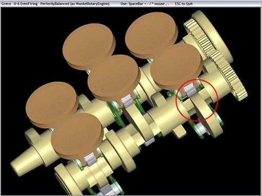
The U-6 Pattakon GRECO engine you quoted is:
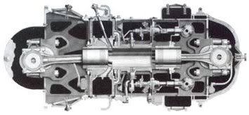
The most compact design I know
It is absolutely balanced (not just as I-6 or V-8 but absolutely as the Wankel rotary engine)
It can use a unique cylinder head, if desirable (like VR-6 of VW)
It can be reduced to a U-4 full balanced - even firing arrangement (removing a pair of cylinders and rotating the cams)
It can turn to a 12 cylinder by just adding six pistons and a cylinder head at the bottom.
If the only problem is the twisting of the drive shafts, all you need to do is to increase the distance of the two drive shafts and the size of the two synchronizing gears. This way you can increase the minimum section of the drive shafts as much as you like.
You write:
The bearings on the guides may be able to handle the load. This is not what I was saying. I said the stop start operation, which will cause wear at the ends of travel. This is where you need the greatest of acuracy on the side load direction change. Too much wear at this point will cause an audible knock. Any comments?
The side rollers begin to decelerate right after the middle of the stroke. I.e. they have plenty of time to completely stop at TDC and then progressively to start accelerating at the opposite direction. Then again, after the middle stroke the process repeats. Another way to reduce inertia of the roller is to have the pin on the wall or the cam and the ring on the piston. Such use is shown in the animation http://www.pattakon.com/greco/GrecoS...leShaftPin.exe.
You write:
The cam design we are using is of a size that reduces the change of bearing speed over the cam face to a point that is reliable. Do you think that the GRECO engine doesn't require the same type of operation given the application and loading is the same?
The only way to reduce the change of bearing speed is by shortening the piston stroke, either in Revetec design or in any other design. In my previous reply I calculate the maximum and minimum speed of the rollers rolling on the cam. Unless I get your writing wrong.
You write:
When a GRECO single cam engine's main bearings contact the drive cam to induce rotation they must contact at an angle to provide rotation. The side thrust generated from this loading is transfered to the guide bearings which need to handle the load, sometimes it is equal when a 45 degree angle is experienced from the piston bearing load contact. As a rule.... over 30 degrees of deviation from the piston(on a single cam engine) causes too much side thrust and is not desirable due to guiding load handling requirements. Given that 30 degrees is the desireable limit for reliability, the result is a low torque lever similar to a swash plate type of arrangement (great as a driven pump but not a drive motor due to high loading of components). This is why I prefer counter rotation of two or three cams. Any comments in this area anyone?
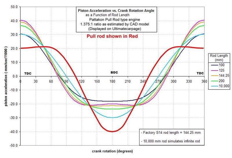
The single lobe cam can be increased in diameter as desirable. In the following plot the three cams are for the same piston stroke.
 Increasing the size of the single lobe cam, you can get as small thrust loads as you want. It is, as always, a matter of compromise.
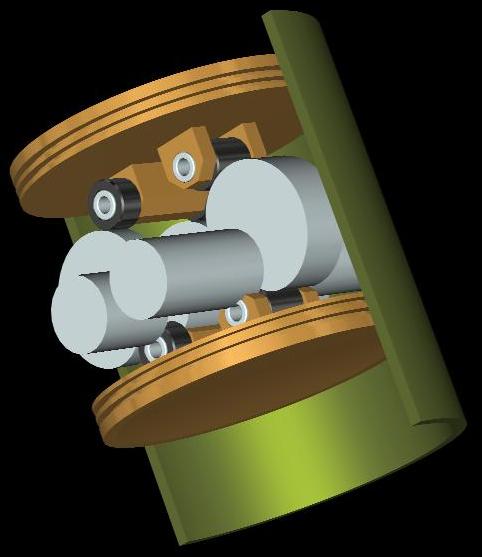
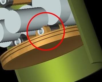
You write : Manolis: The design you just showed has the piston bearing boss inbedded into the shaft and it is not at BDC yet. The bearings are too small to handle the type of loads from a piston/capacity of that size. The final design will not be as compact as shown and I'm looking forward to seeing how they address this in final designs as it may relate to some components in our engine
.
The rollers are small in diameter but you can use more than three rollers per piston, in parallel (i.e. you can use, as the stroke is too short, three cam lobes in parallel on the one drive shaft and two on the other drive shaft, that is five small rollers in parallel per piston, which distributes the loads on the wide piston directly to the cam lobes making the piston light and nevertheless strong). This way the compactness can remain as shown.
You write:
Looking into the future of how this engine may be configured for production I performed some basic bearing calculations and refered back to data from our own product plus consulted information from our SKF bearing database.
To make the bearings reliable for consumer products the bearings require to handle full loads at the required top RPM for around 5,000+ hours I searched our database. The only bearings that I found in the marketplace at a reasonable cost for manufacture that I have found are cylindrical roller bearings or oil pressure fed rollers (Maybe a bit hard to do but not impossible).
The bearings must be encapsulated in a case due to the fact that the bearing outer wall is too hard and brittle for this type of application, and have a case wall thickness of approximately 2.5mm. I have tried bearings straight on a cam and they fail due to impact shock causing the outer cases to crack. On calculating the operation application and the encapsulation of the bearings, a bearing selection would lead me to selecting a bearing for roughly the capacity shown of a diameter of no less than two and a 1/2 times the size shown in the models. Does anone know of alternative bearings that can be used as I'm very interested in this area?
The bearings being a lot larger changes the configuration to a point that a production model would not be as compact as the one in the concept design. Any comments?
Please Note: I'm not criticizing the design concept. Just looking at compactness of a production model for my reference.
I do realise that they are just models and they may not be displaying their latest designs.
The basic theory looks OK at this point but I cant see a production model being as compact as shown. I maybe wrong.
A final running engine design will have to be made and tested for reliability, at which point we can compare sizes :-)
We have had 4 complete engine versions running and are designing our 5th series of engines now. Wait till you all see how compact our new engine is! It will be on our website next week!
I'm not going to comment any further on other issues as I've spent 10 years researching roller based piston engines and I don't want to disclose any more information gained from our development program that has come as a great expense to our company.
It's hard to compare a concept engine to an engine that has been developed over 10 years, built an tested. What do other people think of the GRECO engine in design? Is there any other comments out there from anyone on their design/prolems/benefits as it may relate to some components in our project?
You know the problems. One of them is the roller bearings reliability. The present state of the art cannot yet guarantee such roller bearings. Maybe tomorrow, and hopefully at an affordable price.
So, it is a matter of new technology.
On the other hand, the PRE engine is based only on yesterday, conventional, tested technology.
Thanks
Manolis Pattakos


 Reply With Quote


 See also the file