Me and a classmate got an assignment about a month ago. We would have to redesign the rear suspension geometry to fit to two needs:
- Adjustable ride height for varying conditions (for example track and road)
- All the other things should be easily adjustable
We went to work with analyzing the current layout. We found that it uses a so called De-Dion suspension now. The unsprung weight of this is quite high and can affect handling negatively. Also it is quite hard to adjust anything,except for the shock absobers.
The simple sketches we made to work from and use as reference:
Then we set our own demands to the new suspension. It had to be relatively easy to design and build and as light weight as possible.
We looked at various design options:
- Double Wishbone
- Multi-link
- MacPherson
- Any of the above combined with Citroën's Hydropneumatic system.
We cut these options down to two options that we thought were best. The Double Wishbone and the MacPherson with Hydropneumatic. The Multilink suspension would be to difficult to create. It would involve an enormous amount of wrok on the frame/chassis, that wouldn't be justified by the advantages. The MacPherson with normal shocks would be too heavy and not adjustable easy enough.
After that we made our final choice in a debate with the school / teachers. We chose for the Double Wishbone layout. It was not economical to use Hydropneumatic's. The weight would be too big and the system's pumps and lines would likely not fit in the engine bay without major changes.
This phase of the design process was done for now, now we started work on a Planning and a document with what we would do, the risks, costs etcetera. The school found it ok and we started out with the work.
Because there was no 3D-CAD model available of the rear section of the frame, we had to make one. We took every measurement we could think of and set to work. My mate sketched it and I measured it. Within an hour we were done. We also looked up the kind of steel used in the chassis and the inside thickness of the pipes.
The following 3D-CAD drawing was then made by me in a weekend's time.
The drawing features the chassis from the passenger compartiment to the back.
After this was done we started sketching more detailed idea's about the chassis modifications that would be needed to suspend the wishbones. We made many sketches and after a lot of coffee and calculations we found that it would look like this according to our preffered adaptations:
The steel used for our adaptations is the same as is used for the chassis,namely steel-360.
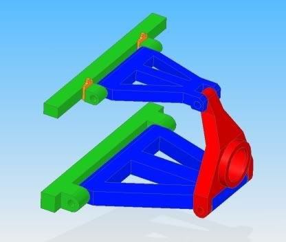
Because of the extremely busy times with other subjects, we had to slow this project down for a week. After this we got back to calculating and drawing again. We are now not completely finished but have done most of the work. We achieved this result:
We now need to calculate what shocks to put under it and how to connect the axles onto this. This will be our task for the weekend. Next tuesday we have a presentation for various teachers and high people of school again. In this meeting we present our solution. After this the school will make a decision if they will use our design, but I allready got hints that it is likely to be funded. The parts would be CNC'ed and mounted and we will probably have to do the welding ourselves (TIG).
Hope you enjoyed it as much as I did,
Sjoerd

 Reply With Quote