
 Ultimatecarpage.com
> Cars by brand
> Italy
> Ferrari
Ultimatecarpage.com
> Cars by brand
> Italy
> Ferrari
 Daytona SP3 Daytona SP3
|
| Ferrari Daytona SP3 |
| Article | Image gallery (56) | Chassis (3) | Specifications |
|
|
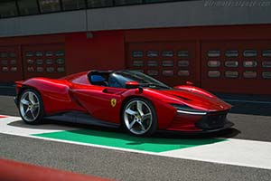
<< Prev Page 3 of 3  To ensure that Daytona SP3 drivers feel entirely at one with their car, its engineering draws heavily on the ergonomics expertise Maranello has developed in Formula 1. The fact that the seats are integrated into the chassis means that the driving position is lower and more reclined than in the other Ferraris in the range. In fact, the position is very similar to that of a single-seater. This helped reduce weight and keep the car’s height to 1142 mm, which in turn reduces drag. The adjustable pedal box means each driver can find the most comfortable position. To ensure that Daytona SP3 drivers feel entirely at one with their car, its engineering draws heavily on the ergonomics expertise Maranello has developed in Formula 1. The fact that the seats are integrated into the chassis means that the driving position is lower and more reclined than in the other Ferraris in the range. In fact, the position is very similar to that of a single-seater. This helped reduce weight and keep the car’s height to 1142 mm, which in turn reduces drag. The adjustable pedal box means each driver can find the most comfortable position.The Daytona SP3’s steering wheel features the same Human-Machine Interface (HMI) already seen on the SF90 Stradale, Ferrari Roma, SF90 Spider and 296 GTB, continuing the Ferrari “hands on the wheel, eyes on the road” philosophy. Touch controls mean that drivers can control 80% of the Daytona SP3’s functions without moving their hands, while a 16” curved HD screen relays instantly all driving-related information. Both the Daytona SP3’s chassis and bodyshell are made entirely from composite materials, a technology derived directly from Formula 1 that delivers excellent weight and structural rigidity/weight ratio. In order to reduce the car’s weight to an absolute minimum, lower the centre of gravity and guarantee compact architecture, several components, such as the seat structure, were integrated into the chassis. Aeronautical composites were used, including T800 carbon-fibre for the tub which was hand-laid up to guarantee the correct amount of fibre for each area. T1000 carbon-fibre was used in the doors and sills, and is essential to cockpit protection as its characteristics make it ideal for side impacts. Kevlar® was also used for areas which are most subject to impact, thanks to its resistance characteristics. Autoclave curing techniques mirrors that of Formula 1, taking place in two phases, at 130° C and 150° C, with the components vacuum-bagged to eliminate any lamination defects. A specific tyre was developed with Pirelli for the Daytona SP3: the new P Zero Corsa was optimised for both dry and wet performance with a particular focus on the car’s stability in low grip situations. The new Icona is also equipped with the latest version of Ferrari’s SSC – 6.1 – which, for the first time on a mid-rear-engined V12, includes the FDE (Ferrari Dynamic Enhancer) to increase cornering performance. This lateral dynamics control system acts on the brake pressure at the callipers to control the car’s yaw angle in on-the-limit driving and can be activated in ‘Race’ and ‘CT-Off’ modes on the Manettino. The adoption of a mid-rear architecture and composite chassis also optimised weight distribution between the axles, concentrating the masses around the centre of gravity. These choices, combined with the work done on the engine, deliver record-breaking weight/power ratio and 0-100 km/h and 0-200 km/h acceleration figures. The objective with the Daytona SP3 was to introduce aerodynamic solutions that would make this the Ferrari with the highest level of passive aero efficiency ever. This required painstaking attention to detail when designing the radiating masses for efficient heat dissipation. Management of hot air flows was thus vital to defining a layout that was as integrated as possible with the overall aerodynamic concept. The increase in the F140HC’s engine power output meant a corresponding increase in the thermal power that had to be dissipated and thus an increase in the radiating masses for the coolant. To allow for the aerodynamics solutions required for the front end meant concentrating development on cooling efficiency first and foremost. Thus detailed work went into the design of the fan housing, the opening on the underbody to evacuate hot air and the intake duct which were all optimised to avoid having to increase the size of the front radiators. Considerable research went into the design of the flanks which benefitted from the layout of the radiating masses for gearbox and engine oil being shifted towards the centre of the car. This solution paved the way for the integration of side channels into the doors, allowing the intake ducts for the radiators to be moved forwards in the chassis. As a result, the front wing creates an ideal section for the intake ducts and captures fresh air that is also highly efficient in terms of cooling the radiators. The high level of integration of aerodynamic functions into the design is demonstrated by the engine cover, which features a central backbone structure to channel fresh air into the engine intake as well as provide outlets to vent hot air from the engine bay. The engine air intake is at the base of the backbone design to shorten the distance to the air filter and minimise losses. The longitudinal slots that separate the backbone section from the single-piece rear bodywork dissipate engine heat and capture fresh air thanks to their interaction with the vents located between the blades on the rear bumper. The layout adopted for thermal management created areas that the aerodynamics team could thus exploit to maximise overall efficiency. This was achieved by focussing on perfecting the integration between volumes and surfaces and by the introduction of new concepts for the underbody that function in in synergy with the upper body without needing to resort to active aero solutions. The front of the Daytona SP3 is a strikingly harmonious melding of form and function. Either side of the central radiator grille are intakes to the brakes ducts and to the channels that vent through the outlets either side of the bonnet to create a blown duct that contributes to front downforce generation. Below the headlights are two aero flicks which increase downforce. The vertically stacked winglets inside the corners of the bumper guide the airflow into the wheelarch, creating an inwash that reduces drag by realigning the flow along the flanks and contains the turbulence generated by the wheel wake. The blown geometry of the front bumpers is not the only element that manages the flow over the flanks to reduce drag. The spoke profiles of the wheels also contribute, as does the vertical design of the flank itself. The former increase the extraction of air from the wheel well and realign the wake with the flow along the flanks. The ample surface area of the latter acts as a barge board to keep the front wheel wake close to the surface and reduce the transverse size of the wake and thus drag. The barge board design also hides a genuine aero channel from the front wheel well that vents ahead of the rear wheel. This solution helps extract more floor performance to the benefit of both downforce and drag. The developments on the underbody were designed to boost the entire floor performance, with the introduction of a series of devices dedicated to generating localised vorticity. Importantly, lowering the height of the underbody meant moving the peak suction closer to the road surface, boosting the efficiency of the devices that exploit ground effect. Two pairs of curved profiles ahead of the front wheels exploit their relative angle to the air flow to generate powerful yet stable vortices which interact with the underbody and the front wheels to develop downforce and reduce drag. Other vortex generators were optimised and positioned in order to virtually seal the front underbody. The outer vortex generator is installed right on the edge of the chassis on the inner wheelarch aperture and has the same effect as a Formula 1 barge board: the vorticity created shields the underbody from the effect of the wake of the front wheel, thereby reducing interference with the more efficient flow created by the central section of the floor. The most important development area for downforce was the rear spoiler. To correctly balance front and rear downforce the engineers fully exploited the opportunity created by the repositioned engine air intake and the new rear taillight design. These two solutions meant that the spoiler could be extended to occupy the entire width of the car. Its surface was not only increased in width, but the lip was also lengthened towards the rear which helped increase the downforce without penalising drag. The most innovative solution, as well a defining characteristic of the car, can be found at the rear of the underbody: floor chimneys are connected to two integrated louvres in the rear wings by vertical ducts. The natural suction created by the curvature of the wings maximises air flow through the ducts and creates a fluid-dynamic connection between flows over the underbody and the upper bodywork. This feature brings three direct benefits: firstly, it reduces the blockage of the underbody by increasing the flow under the front underbody, increasing downforce and shifting the aero balance forwards to improve turn-in. Secondly, the increase in local acceleration of the flow created by the geometry of the intakes on the floor generates a very strong suction which improves rear downforce. Lastly, the rear spoiler also benefits from the additional flow coming from the louvres on the rear wing. The final area of development was to increase the diffuser’s expansion volume, both in the vertical and horizontal plane, thanks to installing the exhaust pipes in a high, central position. The space that was freed up centrally could thus be dedicated to a solution similar to a double diffuser. The diffuser in fact permits the expansion of the flow on two distinct levels and gives a strong connotation to the rear, creating a bridge shape that seems to float in the tail’s volume. The concept exploits the high energy from the central area of the flow to efficiently channel the air both inside and outside of the central ‘bridge’ structure. This means the flow that passes outside the central channel energises the one inside, boosting the efficiency of the diffuser as a whole. The Daytona SP3 has a wraparound windscreen in which the glass extends all the way to the start of the removable hard top. A nolder is integrated into its upper seal to accurately direct the flow over the header rail when driving without the hard top. The middle of the roll hoop area dips to follow the shape of the rear bodywork buttresses and the engine cover and thus minimises the possibility of the wake deflected towards the rear header rail tumbling back into the area between the seats. The airflow at the rear of the side windows is channelled by the rear trim behind the headrests towards a centrally recessed slot protected by the windstop so that it is vented outside the cockpit. << Prev Page 3 of 3 |
| Article | Image gallery (56) | Chassis (3) | Specifications |
| All Cars - Contact us - Privacy Statement - Top | © 1998 - 2026 Ultimatecarpage.com |